Filling-pressure monitoring system

with automatic regulation of the filling pressure and power of p-joint-sealing cushions/V (valve) during installation.
General
The sealing efficiency and service lifetime of p-joint-sealing systems are directly related to filling pressure, which is temperature-dependent, and lateral movement along the x-axis.
It is therefore important to:
- adhere strictly to the installation specification, VO 60.02 Pressure-filling of Sealing Cushions with a Valve for Expansion and Movement Joints, and to provide proof of tightness.
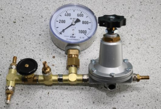
- reach the permissible pressure filling for reusable p-seals for movement joints (type L: 300 – 350 mbar and type S: 150 – 200 mbar (20°C +10°C)) during installation. This can be achieved by using the filling-pressure monitoring system Art. No. 86.01 p-AK-MSMO, for example.
- set up the filling-pressure monitoring system Art. No. 86.01 p-AK-MSMO for permanent regulation of filling pressure and power after installation (because pressure fluctuates as a consequence of movement along the X-axis in summer and winter, amongst other factors). Ceiling or wall Installation is recommended.
- carry out a visual inspection of the filling pressure (tightness) of the reusable movement-joint p-seals in the course of routine joint inspections, adjusting the filling-pressure where necessary.
2 Pressure gauge with diaphragm capsule "Gas"
![[Translate to English:] 2 Kapselfeder-Manometer Gas](/fileadmin/user_upload/Icons/2_Kapselfeder-Manometer_Gas.png)
- With zero adjustment
- Optional overpressure and/or underpressure safety
10 x FSD (full scale deflection)
- Extremely low measuring range from 0/6 mbar
- GOSSTANDART-certified
Technical specifications:
- Type D4
- Nominal size 100
- Accuracy class (EN 837-3/6): 1.6
- Display range (EN 837-3/5):
NG 63-100 0/25 to 0/1000 mbar,
and all corresponding vacuum and
compound ranges with
over-pressure protection
Application area:
Static load: full scale value
Dynamic load: 0.9 x full scale value
Overload safety: 1.3 x full scale value
Operating temperature range:
Medium: Tmax = +60°C
Ambient Tmin = -20°C
Tmax = +60°C
Temperature performance:
Indication error when the temperature of
the measuring system deviates from the
normal temperature of +20°C:
Rising temperature approx. ± 0.6%/ 10 K
Falling temperature approx. ± 0.6%/ 10 K
of the full scale
Degree of protection:
NG 63/160: IP 33 (EN60529)
NG 100: IP 54 (EN60529)
Mode of operation of the p-AK-MSMO filling-pressure monitoring system

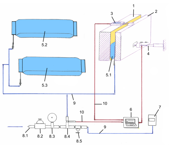
Key
8 p-AK-MSMO Monitoring system (for pressure filling and monitoring)
(For assembly unit: reusable p-joint-sealing system)
8.1 Pressure inlet valve
8.2 Precision pressure controller
8.3 Pressure gauge Ø 100 mm 0–1000 mbar
8.4 Connection: pneumatic tubing for connection to the reusable p-sealing system
(for accessory parts, see PI 60 |05)
8.5 Mini shut-off valve
9 Connection: pneumatic tubing for connection to 85.1 PaK tightness control system (7)
(Data logging after pressure filling)

2. Functional example
(Fibre Optics CT GmbH
est setup No. 3,
Test Report 263/ 2020)
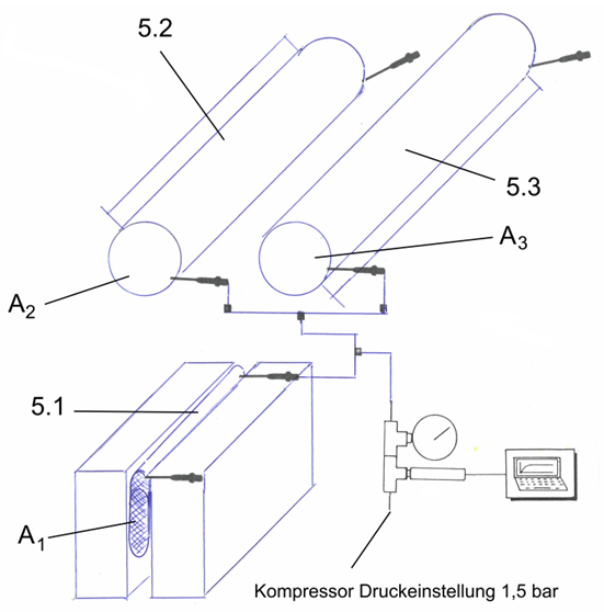
The following 3 reusable p-joint-sealing cushions (test samples) are connected to one another via the precision pressure controller (8)
5.1 Type L, length lV = 70 cm
Joint width: 3 cm
Pressing surface: 9 cm
5.2 Type S, length lV = 409 cm Ø 18.15 cm and
5.3 Type S, length lV = 500 cm Ø 18.15 cm
The precision pressure controller has been set to
250 mbar / 20 °C filling pressure and max. tolerance 300 mbar, in accordance with the required filling pressure for sealing cushions (test sample 5.1/ width 134 cm)
Aim: In order to make the installation process of the sealing system simpler and more economical in the case of joints longer than 30 m, at least two joint-sealing cushions (VV) should be connected to each other and inflated simultaneously in accordance with the installation instructions.
5.1 Test sample Type L
width bL 13.5 cm length lV 74 cm
volume V = 1863 cm³
Movement at temperature (20 ± 5 °C): none
5.2 Test sample Type S
width bL 28.5 cm,
length lV 409 cm
volume V = 105766 cm³
Movement: none
5.3 Test sample Type S
width bL 28.5 cm,
length lV 500 cm
volume V = 129300 cm³
Movement: none
Example: Filling times for simultaneous inflation
(Test diagrams taken from FibreOpticsCT GmbH Test setup No. 3
Filling times for test samples A1, A2 and A3, Protocol No. 260.1 /2020)
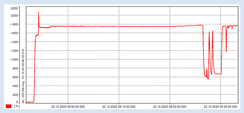
Example: Pressure force for the purpose of verifying tightness
(Test diagrams taken from Fibre Optics CT GmbH
Test setup No. 3 Test Report No. 263 /2020)
Sealing cushions
1. Pressure filling with air for a total volume of 235250 cm³ = approx. 60 minutes
For a joint with an average width of 3 cm, this corresponds to
126 x 0.69 m = a total joint length of ~ 87 m
2. After the pressure force was exerted for approximately 2 hours in order to verify tightness,
the pressure was gradually reduced to 225 mbar and then held for ~ 20 min before the test was ended.
![[Translate to English:] Präzisionsdruckregler (Fülldruck-Monitoringsystem mit automatischer Fülldruck- & Kraftregulierung für p-Fugen-Abdichtkissen (Ventil))](/fileadmin/user_upload/Icons/Praezisionsdruckregler.png)
![[Translate to English:] Präzisionsdruckregler Durchflusscharakteristik](/fileadmin/user_upload/Icons/Durchflusscharakteristik.png)
![[Translate to English:] Hysterese](/fileadmin/user_upload/Icons/Hysterese.png)


