Filling-pressure monitoring system (during installation)
p-AK-MSBE Filling-pressure monitoring system with automatic regulation of
the filling pressure and power of p-joint-sealing cushions/V (valve) during installation.
Filling-pressure monitoring system with automatic regulation of the filling pressure and
power of p-joint-sealing cushions (valve) during installation (ceiling or wall mounting)
- For simple visual control during inspection and maintenance
- For controlling the target pressurefilling of 150 mbar to 300 mbar from below
General
The sealing efficiency and service lifetime of p-joint-sealing systems are directly related
to filling pressure, (which is temperature-dependent) and lateral movement along the x-axis.
It is therefore important to:
- adhere strictly to the installation specification, VO 60.02 Pressure-filling of Sealing Cushions with a Valve for Expansion and Movement Joints, and to provide proof of tightness.
- reach the permissible pressure filling for reusable p-seals for movement joints (type L: 300 – 350 mbar and type S: 150 – 200 mbar (20°C +10°C)) during installation. This can be achieved by using, for example, the filling-pressure monitoring system Art. No. 86.01 p-AK-MSMO.
- set up the filling-pressure monitoring system Art. No. 86.01 p-AK-MSMO for permanent regulation of filling pressure and power after installation (since pressure fluctuates as a consequence of movement along the X-axis in summer and winter, amongst other factors). Ceiling or wall Installation is recommended.
- carry out a visual inspection of the filling pressure (tightness) of the reusable p-seals for movement joints in the course of routine joint inspections, adjusting the filling-pressure where necessary.
Design:
Measuring element: Capsule spring,
CuBE alloy
Movement: Brass
Zero adjustment: From the front
Seal: NBR (perbunan)
Dial: Aluminium, white,
with black markings
Pointer: Aluminium, black
Housing: Stainless steel 304
Bayonet ring: Stainless steel 304
Window: Instrument glass
Panel-mounted devices
(types D 431/451)
Plastic (acryl
glass PMMA)
Technical specifications:
- Type D4
- Nominal size 100
- Accuracy class (EN 837-3/6): 1.6
- Display range (EN 837-3/5): NG 63-100
0/25 to 0/1000 mbar, and all corresponding
acuum and compound ranges with
over-pressure protection
- Application area:
Static load: full scale value
Dynamic load: 0.9 x full scale value
Overload safety: 1.3 x full scale value
Operating temperature range:
Medium: Tmax = +60°C
Ambient: Tmin = -20°C
Tmax = +60°C
Temperature performance:
Indication error when the temperature of the measuring system deviates from the normal temperature of +20°C:
Rising temperature approx. ± 0.6%/ 10 K
Falling temperature approx. ± 0.6%/ 10 K
of the full scale
Degree of protection: NG 63/160:
IP 33 (EN60529)
NG 100:
IP 54 (EN60529)
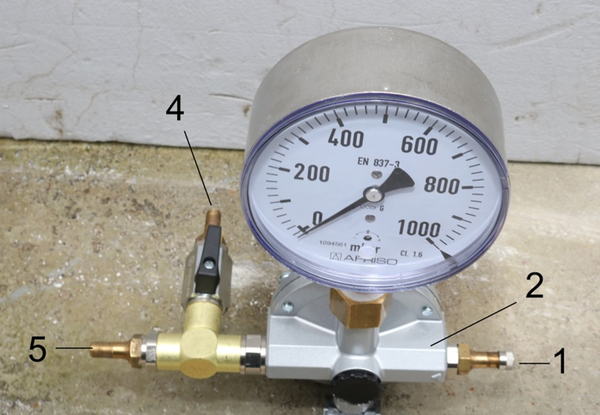
Key
p-AK-MSBE Filling pressure
indicator (for monitoring)
(For assembly unit: reusable
p-joint-sealing system)
1 Pressure inlet valve
2 Precision pressure controller
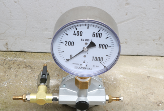
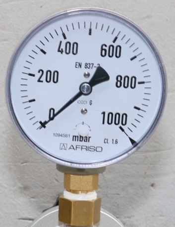
3 Pressure gauge Ø 100 mm 0–1000 mbar
4 Connection: pneumatic tubing for connection
to the reusable p-sealing system / valve
5.1 Where necessary, connection
(via pneumatic tubing) to
Art. No. 86.03 p-AK-GMA
Hazard alarm system
5.2 Pressure adjustment
(pressure inlet valve)
in the event of pressure loss
Type L < 300 - 350 mbar
Type S < 150 - 200 mbar
Note:
6 Mounting bracket
(for wall or ceiling attachment)
7 Rotary knob for pressure setting
(pressure setting fixed by means
of a locknut) is only used when
pressure filling takes place via
the pressure inlet valve (1)
2. Functional example
(Fibre Optics CT GmbH test setup No. 3, Test Report 263/ 2020)
Test setup for
"Thermal resistance of the fully automatic monitoring system"
(Protocol No. 259 B/ 2020)
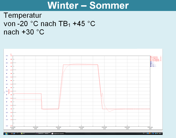
- Cycle 1:
At high temperatures TB1 +20 °C after +45 °C
+45 °C after +20 °C
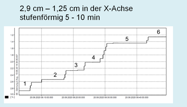
stepwise lateral joint movements from 3 cm to 1.25 cm (narrowing),
at ambient temperatures acc. to "winter-summer hypothesis" after a dwell time of 24 h
- Cycle 2:
At low temperatures TA1 +20 °C after -5 °C
TA2 -5 °C after -30 °C
-30 °C after +20 °C
stepwise lateral joint movements from 3 cm to 6 cm (widening) and
back to 3 cm at ambient temperature acc. to "summer-winter hypothesis"
Procedure
Tests to establish the reliability of performance of the monitoring system (in controlling pressure-filling and monitoring) at high and low temperatures.
In the tests, the monitoring system unit and a container with water were placed in a climate chamber, to simulate actual operational conditions, in accordance with IEC 60068-2-14 section Nb (Fig. 1).
In operation, the monitoring unit is attached to the wall or joint edge and is connected to the sealing system by means of a pneumatic line.
The components are only used for the installation of the reusable p-seal and for the verification protocol of "sealing tightness and permissible filling-pressure", and are located outside the climate chamber.
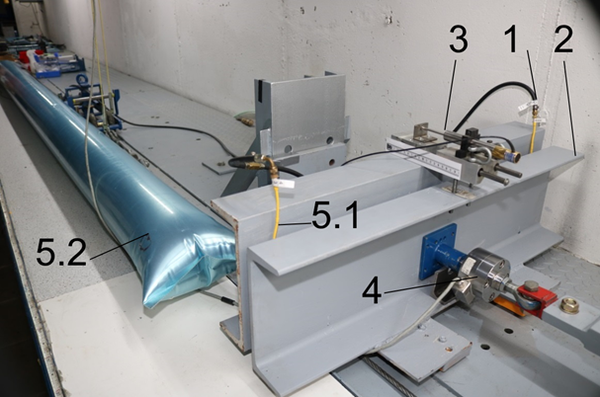
Key
1 Movement-joint seal
2 Slideable weight to simulate lateral
deflection in the movement joint
3 Cylinder for measuring movement
4 Cylindrical pressure load cell
5 Test sample reusable p-seal,
uncoated
5.1 Test sample type L width bL 13.5 cm,
length lV 74 cm
Movement at temperature (20 ± 5 °C)
5.2 Test sample type S width bL 28.5 cm,
length lV 409 cm
Without movement

![[Translate to English:] Durchflusscharakteristik Präzisionsdruckregler](/fileadmin/user_upload/Icons/86-2_Durchflusscharakteristik_Praezisionsdruckregler.png)
![[Translate to English:] Hysterese Präzisionsdruckregler](/fileadmin/user_upload/Icons/86-2_Hysterese_Praezisionsdruckregler.png)
![[Translate to English:] Fülldruck Monitoringsystem](/fileadmin/_processed_/b/a/csm_Fuelldruck_Monitoringsystem_Ansicht_von_oben_f5c4f28360.png)


